| EMR 18 SERIES | |
| FEATURES |
|
|
|
SPECIFICATIONS
Types |
18 |
| Contact Form | 1A |
| Contact Rating Maximum switching power Maximum switching voltage Maximum switching current Maximum carry current |
10VA 100VDC 0.5A 1.0A |
| Contact Resistance,Initial | 150 m |
| Contact Material | Rhodium |
| Life Expectancy (Contact) (Signal level load ref 10VDC,10mA) |
10 |
| Insulation Resistance( |
100 |
Timing (at
nominal VDC, 25Hz drive, 50% |
1.0 ms 0.5 ms |
| Dielectric Voltage Coil to contact Across contacts |
3000 VAC 200 VDC |
| Shock Resistance | 30G Min. |
| Electrical Life at Rated Load | 106 |
| Temperature Range | -10 |
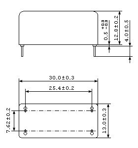
DIMENSIONS: UNIT:mm
| EMR18
(FORM 1A) Magnetic Shield Open Type |
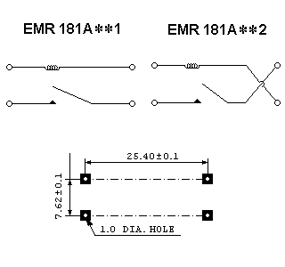
Wiring
Diagram and PCB Layout (Top View) |
 |
 |
PART NUMBERING SYSTEM
EMR 18 1 1 A 08 | | | | | | | | | | | +--- LAYOUT TYPE | | | | +------- COIL RESISTANCE: 12:12| | | +---------- CONTACT FORM | | | A:CONTACT a
(NORMAL OPEN) | | +------------- CONTACT NUMBER SET: | +---------------- TYPE: +--------------------- SERIES NAME
Part |
Coil Resistance |
Nomin al Input |
Nominal |
Must Operate |
Must Release |
Maximum |
EMR181A071/2 |
7 |
2.8 |
20 |
15 |
5 |
200 |
EMR181A091/2 |
9 |
3.6 |
20 |
15 |
5 |
200 |
EMR181A121/2 |
12 |
4.8 |
20 |
15 |
5 |
200 |
EMR181A151/2 |
15 |
6.0 |
20 |
15 |
5 |
200 |
EMR181A181/2 |
18 |
7.2 |
20 |
15 |
5 |
200 |