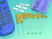
ERF SERIES
| Resettable Fuse ERF SERIES |
|
|
 |
|
| OVERVIEW
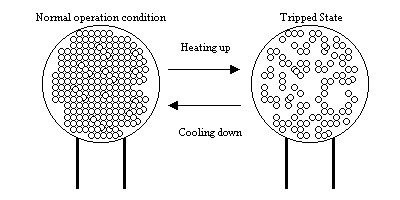
Polymeric PTC resettable fuse devices synergistically integrate the advance polymer material technologies, conductive material science and novel processing engineering. Electrical resistance of such material and devices increases with increasing temperatures. When experiencing “overcurrent and/or over voltage”, the device generates thermal energy (Energy = I*V) and heats up itself. This makes its polymer matrix morphology change from crystalline to amorphous phase and results in a resistance increase of thousand orders of magnitude such that “trip” the electricity. The device will remain hot and stay “tripped” until the fault is cleared and power is removed. (Figure 1)
|
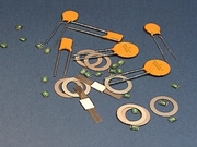
The ECE resettable fuses are made of patented novel polymeric PTC material in thin sheet form. With electrodes and leads attached on both sides, it is placed in series to protect a circuit. At “normal operating condition” the device remains at an extremely low resistance (mini-ohms) and allows the electrical current flow through it without any restriction. When overcurrent condition occurs, the Polymeric PTC material heats up and its resistance increases sharply. Such a sharp resistance increase (to an insulated status) cuts off the current in the circuit, and consequently protects the element and device in the circuit. Upon the fault current being removed, the resettable fuse will be cooled and its resistance will drop to the original extremely low value. The ECE resettable fuse was “resetted” and allows the current through the circuit again.
|
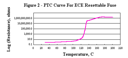
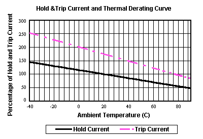
Hold
Current (IH) and Trip Current (IT) of ECE
resettable fuse are rated at 23
|